Hydraulic Turbine
CFD Analysis
Advanced Simulation for Performance Optimization
Advanced CFD Analysis for Hydraulic Turbines
ECS Engineering Consultancy Services provides advanced Computational Fluid Dynamics (CFD) analysis for Pelton, Francis, and Kaplan hydraulic turbines — helping hydro power developers, EPC companies, turbine manufacturers, and research institutions optimize turbine performance under real operating conditions.
Our CFD simulations use ANSYS CFX and ANSYS Fluent — the industry-standard tools — combined with high-quality meshing using TurboGrid and ICEM CFD. We simulate complex phenomena including transient multiphase flow, jet-bucket interaction, rotor-stator interaction, cavitation, and torque fluctuations that are impossible to study through physical testing alone.
Every project includes a comprehensive technical report with velocity contour plots, pressure distribution maps, streamline visualizations, efficiency curves, and actionable design recommendations — ready for client presentations, academic submissions, and government approvals.
⚙ Why CFD Analysis for Your Turbine?
CFD Analysis for All Major Turbine Types
We have deep expertise in CFD simulation of all three major hydraulic turbine families — each requiring unique simulation strategies.
Pelton turbine CFD requires specialized transient multiphase (air-water) simulation to accurately capture jet-bucket interaction, water sheet formation, and torque generation — ECS’s core expertise.
- Transient multiphase (VOF) simulation in ANSYS CFX
- Jet-bucket interaction and water sheet analysis
- Bucket-wise torque contribution study
- Jet deviation and spillage analysis
- Efficiency vs. speed ratio (u/c₁) curve
- Notch effect and backwall interaction study
Francis turbine CFD covers the entire flow path — from spiral casing and stay vanes through guide vanes, runner, and draft tube — including critical rotor-stator interaction analysis.
- Full flow path simulation (casing to draft tube)
- Rotor-stator interaction (RSI) analysis
- Guide vane opening optimization
- Cavitation prediction and sigma analysis
- Draft tube swirl and pressure recovery
- Part-load and full-load performance curves
Kaplan turbine CFD focuses on blade angle optimization and tip clearance effects — critical for achieving high efficiency across the wide range of flow conditions typical for low-head applications.
- Runner blade and guide vane angle optimization
- Tip clearance leakage flow analysis
- Double-regulated (blade + guide vane) optimization
- Flow uniformity at runner inlet analysis
- Efficiency hill chart (cam curve) development
- Cavitation and erosion risk mapping
What Our CFD Analysis Covers
A complete end-to-end CFD workflow — from geometry preparation to final report delivery.
3D model import, geometry cleanup, and preparation for meshing. CAD repair, simplification, and domain setup for accurate simulation.
Structured and unstructured mesh generation using TurboGrid and ICEM CFD — with boundary layer refinement for accurate near-wall resolution.
Transient or steady-state simulation in ANSYS CFX / Fluent — with appropriate turbulence models, multiphase setup, and convergence monitoring.
Analysis of dynamic interaction between rotating runner and stationary components — pressure pulsations, torque fluctuations, and resonance risk.
Prediction of cavitation inception, cavity extent, and erosion risk zones using the Rayleigh-Plesset model — with Thoma sigma evaluation.
Comprehensive technical report with all contour plots, performance curves, numerical data, and specific design improvement recommendations.
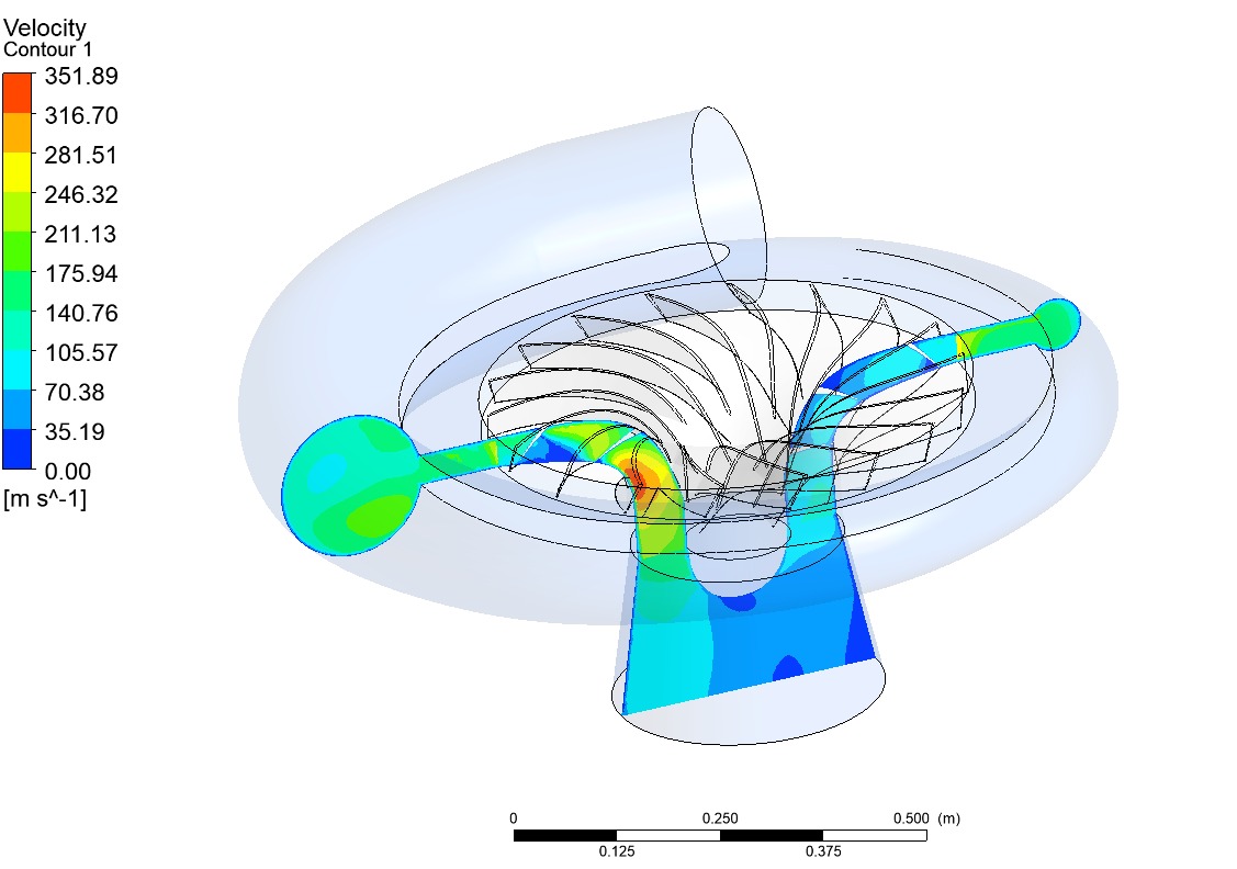
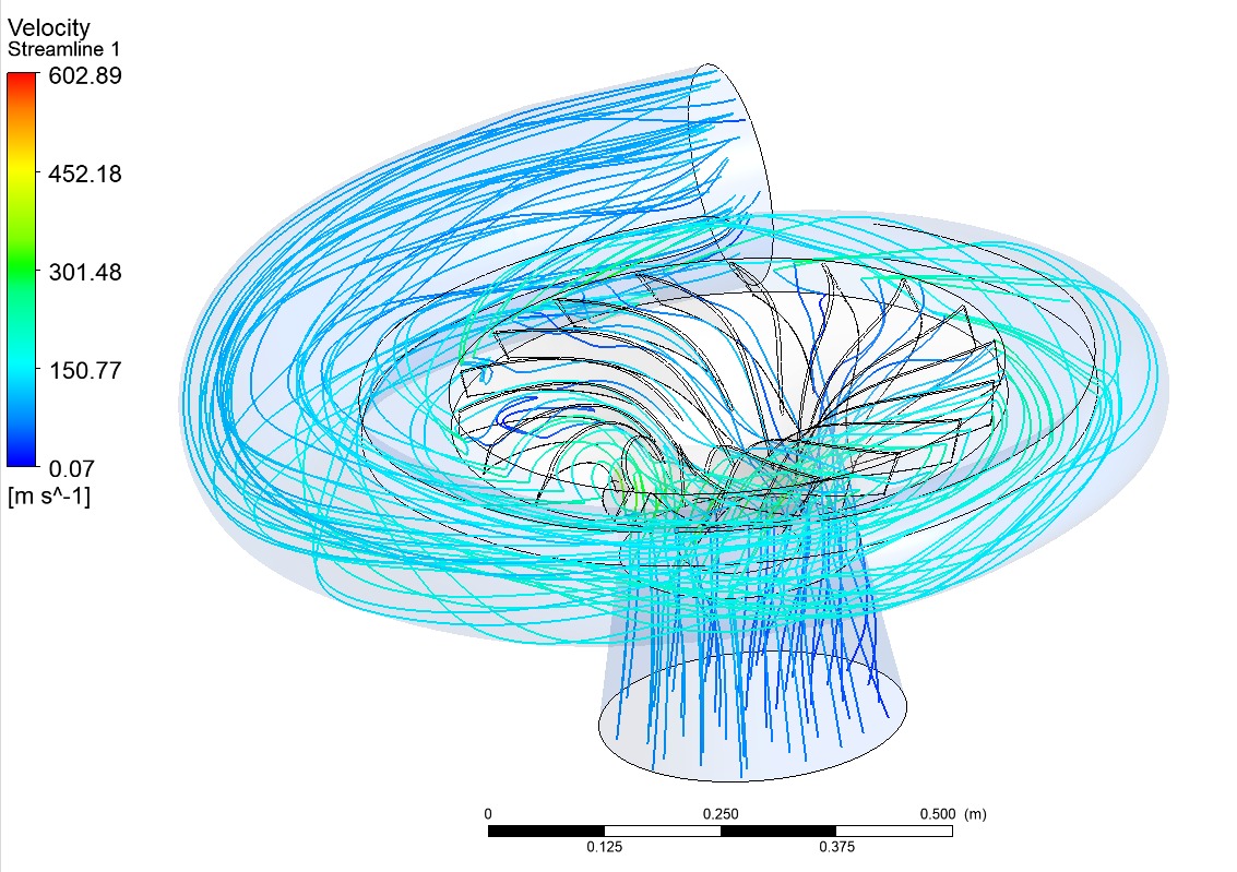
Francis Turbine CFD Simulation — 2 × 500 kW
Real simulation outputs from our completed Francis turbine project — ANSYS CFX transient multiphase analysis. Click images to enlarge.

Key Parameters & Software Used
Industry-standard tools and comprehensive parameter coverage for every CFD simulation project.
📊 Key Simulation Parameters
Software We Use
Our CFD Project Workflow
A structured 6-step CFD process — from your first enquiry to final report delivery.
Requirement Discussion
Turbine type, head, flow, capacity, and specific analysis goals
Geometry & CAD Setup
3D model import, geometry cleanup, and domain preparation
Meshing
TurboGrid / ICEM CFD structured & unstructured mesh with y⁺ control
Simulation
ANSYS CFX / Fluent transient or steady-state run with monitoring
Post-Processing
Contour plots, streamlines, efficiency curves, and data extraction
Report Delivery
Full technical report with results, analysis, and design recommendations
Project Deliverables
Every CFD project includes a complete, professional documentation package — ready for presentations, submissions, and approvals.
Clients We Work With
Our CFD analysis services are used by a wide range of clients in the hydro power and academic sectors.
Need CFD Analysis for Your Hydro Turbine?
Get advanced Pelton, Francis, or Kaplan turbine CFD simulation using ANSYS CFX — with full technical report, contour plots, and design recommendations. Share your turbine details and we’ll respond within 24 hours.
 Facebook
 LinkedIn